A joy of electronics is burning out components. Always buy extra. I burned out a magnetic lock unit while working with an implementation of Google’s makerspace-auth (https://github.com/google/makerspace-auth). As it is electro-mechanical, I decided to take advantage of the situation and pop it open. First let’s see what I went into the situation with.
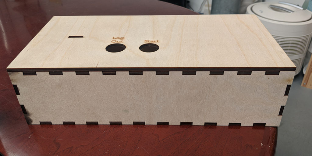
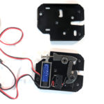
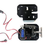
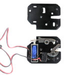
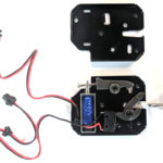
The maglocks in question were identical to this unit:
The provided specs:
– DC 12 V, 2A
– Maximum Continuous Lighting Time: 5s
– The connector type of K02 is SM 2 Pins Plug. K02 has 2 plugs, one female plug for power supply, another male plug for feedback signals.
My initial read is that the lock took 12V power in the female JST SM connector and would trip based on the signal provided to the male connector. Astute readers will have picked up my mistake by now, but let’s continue as I did: assuming I know what I’m doing without writing anything down and checking assumptions! Did I mention always buy extra?
Before powering anything, I wired up the lock to the board. The PCB takes in a 12 V barrel connector and has 12 V outputs, so I jumped power directly into the female plug, and left two jumpers on the signal pin to trip it. I powered up the board, and then tried to trip the lock. Nothing. Weird. Well, not weird to you astute readers, but it was weird to me. I disconnected everything and started to pick up the lock. I say “started to” because it was warm, nearing on toasty.
“Huh. An internal short? Probably not. Let’s assume it was me. What did I do wrong?” First I checked the connectors. Did I mess up male and female? I googled the JST SM connectors to be sure. Nope, got that. Maybe the wires were cross? It wouldn’t be the first time I’ve received products where the wiring was not US standard. I couldn’t tell that from the tools I had. There was definitely a short, connectivity testing proved that. That’s a nice tip, check connectivity between power and ground before turning anything on. If there’s a short there, it’s time to stop and re-assess. Who put the short there?
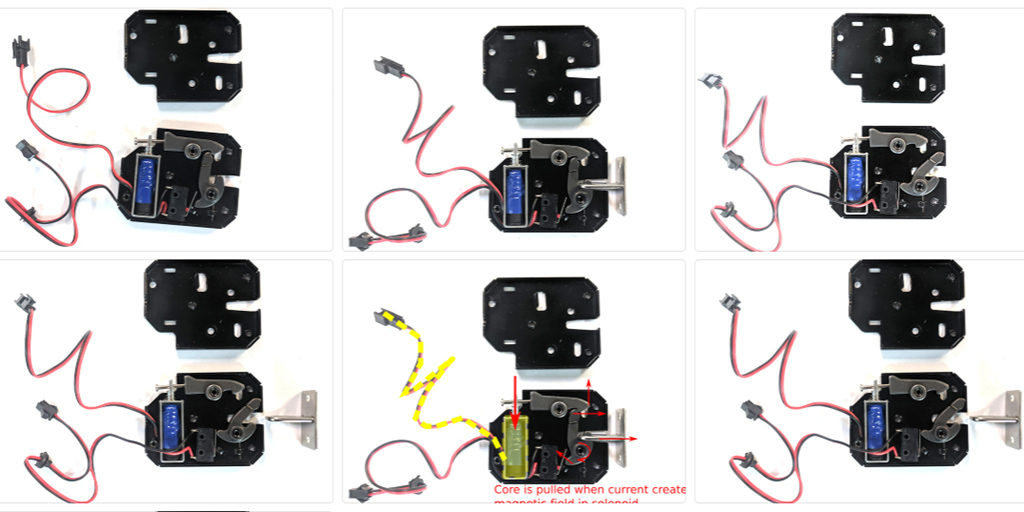
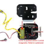
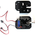
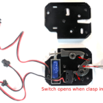
I popped the lock open, it was just three screws. Inside was telling. The female connector went to a solenoid which pulls a rod when power is applied. The male just goes to a mechanical switch which is held closed when the lock is closed. A spring pulls the latch open based on the action provided by the energized solenoid’s magnetic field pulling the pin to center. This also would push anything attached to the latch outward on triggering, making a door swing open. Neat!
So there was an internal short, but it was the intentional kind. Had I performed a connectivity test for shorts before applying power, and I would have found one. The solenoid is just wound copper, so it will present as directly connected conductor. This would have been a clue to not apply power constantly. The lock works by applying 12V, 2A for a maximum of 5s. When I turned the power on, I had 2A running through the solenoid. Most likely this melted insulation between the windings, and created shorts up and down the solenoid, ruining the loops required to induce the magnetic field.
I could have avoided this with a better reading of the specs. The male connector is for feedback, not for triggering. That’s the key information you astute readers picked up that I missed.
A lot of electromechanical motion uses some kind of inductance (a solenoid is an inductor) and a magnetic material to convert electrical energy to mechanical force. This lock is effectively a mechanical relay, when energy is applied, it releases a spring which closes the switch when locked. Any signal is fed into the male pin will come through the wire since it’s just closing a switch, allowing the signal through. Connecting this to a GPIO and ground will provide a signal if the lock is open or shut.
Burning things out is always exciting is some fashion, but it’s always an opportunity to go back and figure out what went wrong. In this case I was lucky, I had extra on hand (did I mention always by extra?) and this was a mechanical part so I could open it up and take a look inside, and I now I know exactly how they work.
~ Contributed by Matt Arcidy of Ace Monster Toys